So I screwed up the ignition wires

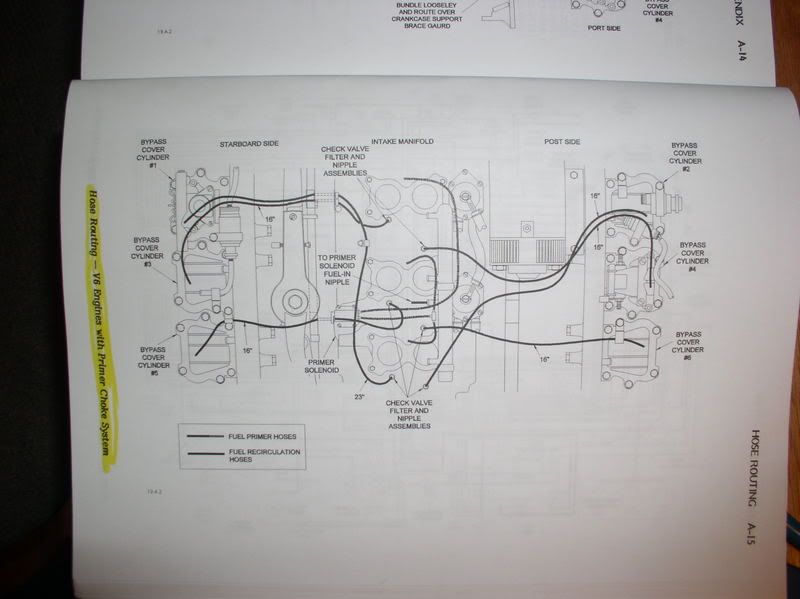
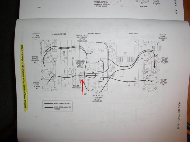
This is the hose routing for the primer (choke) system
Picture253.jpg

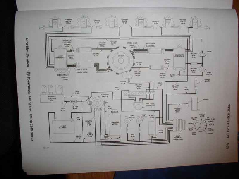
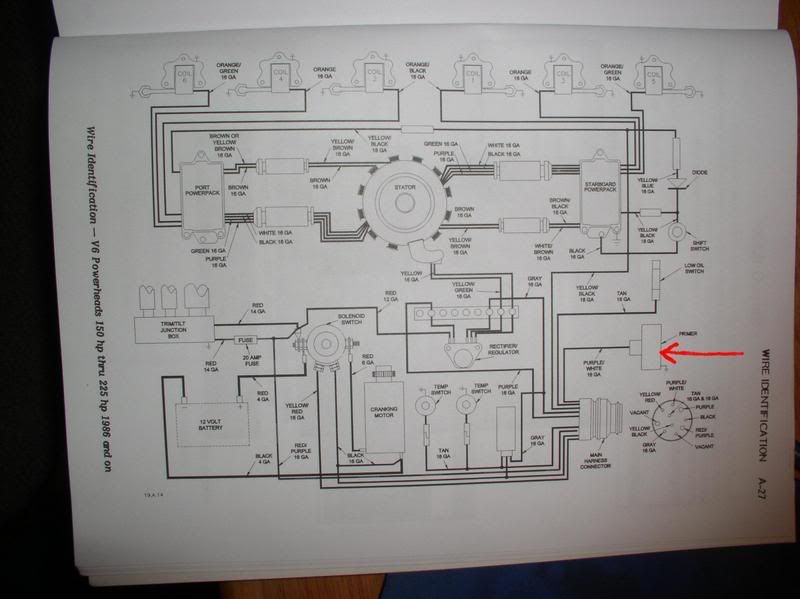
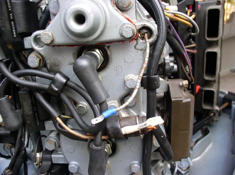
This shows the primer and wire color (purple with white tracer)
Picture256.jpg

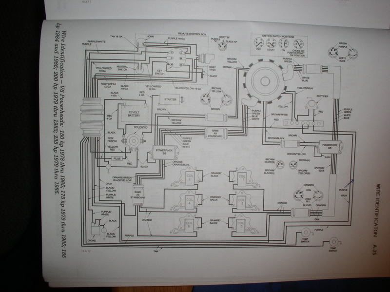
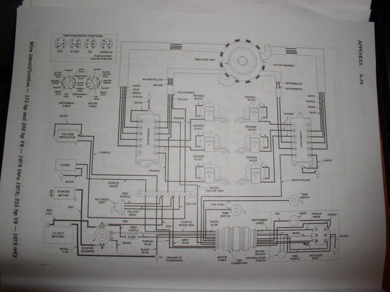
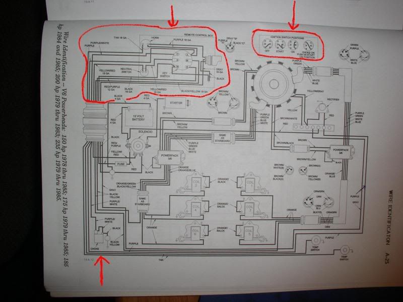
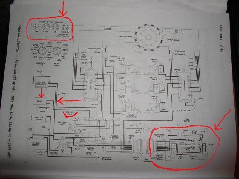
This one and the next, compare wire colors at the switch and motor harness asto what you have.
Picture255.jpg

Note the ignition switches are different in the third and fourth pictures.
Picture254.jpg


Give me a minute and I'll point out the stuff.
 
Picture253a.jpg


Picture256a.jpg


Picture255a.jpg


Picture254a.jpg


The possibility does exist that you need a different ignition switch than what you bought.
Test the old one and see if it works and how the terminals make contact at the different positions (hell it might be good).
 
I also got a new Cig lighter, new recesed handles for the hatches, (I hate them Carragie bolt handles) all new LED brake lights, eletric horn.

All installed and working today!

Just have to figure out the rest of the ingnition I be about tready for the water!!
 
And are the whores (whores, I said whores) (try pimp girls) on board also? ;D
That's it!
Are the pimp girls on board? ;D
 
Not yet! But soon.

I have a new Color Chart plotter coming in 2 days, have to finish off a few small things, and should be ready to dunk.

After the first dunking Iand all goes well, My son is going to give it the first and only wax job that it will ever see!!

Then its Tuna time!! they getting alot here this year!!
 
Yes it is!! But the old owner did 1/2 the boat and it looks like crap, so My sonm going to make them match, then they can go the he!! toghter ;)
 
Just checking to see if you got all the wires hooked up or not.
The purple(s) could be a couple of things.
Is the tach working?
Is the overhead horn working?
Tach not working, it could be the wire for it.
Check the overhead horn by disconnecting it at the motor and with the key "on" (running isn't necessary) ground the wire from the harness to the powerhead.
Picture205.jpg
 
Yes CB called last night and said he has a horn and key switch and looks like the purple goes to the horn.

So what wire is the choke?? I thought it was the purple also??

By the way did I say I hate electric yet??
 
MJ, have you checked out the info at Continuous Wave? This might help:

OMC Outboard Motors

The following color coded wiring is often seen in outboard motors manufactured by OMC. This information was developed by Jim Hebert from factory wiring diagrams. Unfortunately, these diagrams are completely lacking in annotation. The identification of the circuits involved was deduced by the author with the assistance of OMC master mechanic David Zammitt of Lockeman's Boat and Hardware.

A pictorial diagram of the typical OMC ignition switch wiring is available in a separate article. It illustrates the use of these wiring colors.

OMC Under-cowling Wiring
------------------------

(Based on V6 c.1992)

RED = Battery positive
RED with VIOLET stripe = Fused battery supply to ignition switch

BLACK = Battery negative
BLACK with YELLOW stripe = KILL Switch (grounded to stop engine)

YELLOW with RED stripe = START (Ignition switch to starter solenoid via safety switch)

VIOLET = Battery voltage in RUN or START from ignition switch
VIOLET with WHITE stripe = PRIMER solenoid

LT BROWN = ALARM (grounded on alarm)

GRAY = TACHOMETER pulses to gauge from Rectifier/Regulator


OMC Stator Coil / Timer Base Wiring
----------------------

YELLOW / YELLOW with GRAY stripe = Battery Charging Coil AC voltage
to Rectifier/Regulator on Assembly
Engine Block

BROWN / BROWN with YELLOW stripe = Charge Coil to Ignition Power Pack
BROWN / BROWN with BLACK stripe = Second Charge Coil to Ignition Power Pack

ORANGE / ORANGE with BLACK stripe = Power Coil to Ignition Power Pack
or OIS Module

Green / Violet / White = Timer Base to Ignition Power Pack
/ Black with White


OMC Power Trim and Tilt
-----------------------

RED = Battery positive
RED with VIOLET stripe = Fused battery supply to remote controls

BLUE = UP supply to MOTOR
BLUE with WHITE stripe = UP RELAY
GREEEN = DOWN supply to MOTOR
GREEN with WHITE stripe = DOWN RELAY
RED with WHITE stripe = Fused battery to remote switches

BLACK with TAN = Trim SENDER isolated ground
WHITE with TAN = Trim SENDER isolated fused battery positive

***The link to a nice color diagram of the ignition circuit can be found here:

http://continuouswave.com/whaler/reference/ignitionSwitch.html
 
So, under the dash, the purple goes from the ignition to the buzzer/alarm, to the accessories that should turn on with the key, and to the tach.
 
ok so what wires are to the choke??

I thought that was purple?? :-/

Boat runs right now, and there is no buzzer at this time I have to go get one. But CB had said the same thing. He keeps saying he is going to come here with his Multimetter and we get her done.
But he so busy I keep getting pushed to the curb like the trash! :'(

Going to take her for a ride this after noon ;D

Thanks all!
 
Can't you use a test light and push in the choke and see which terminal gets power when you push in the choke. It could also be that pushing in the choke provides ground which you could also check with a test light.
 
Still you think you are a smart a$$??

I think you are!! I never thought of that! ;)

I am getting the boat ready for a ride in 2 hours! Test will have to wait!!
 
Look at the diagrams, purple with white tracer is the choke from the switch to the choke (primer) solenoid.

And grace it depends on the years the motor and harness are. Not always will a color code repeat year to year but generally they will stay the same.
 
MJ post loose ends or not sure about termination locations.
WHAT YEAR WAS THE MOTOR REMOVED FROM THE BOAT AND HP or what year wiring harness did you use.
There are subtile differences in some of the harnesses and motor electrical terminations.
Also are the ignition switch and overheat horn remote mounted from the controls? Pictures suggest this.
 
Back
Top