So I screwed up the ignition wires

macojoe

Administrator
So like I don't have enough to do, I go and mess up the wires to the ignition switch :o

Some how I ziged when I should have zaged??

I did one wire at a time and still screwed it up.

Now as soon as I turn thr power on and then the key motor starts to turn??

Does anyone have the right wireing for the key??

Thanks!!
 
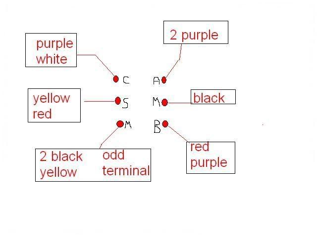
See if any of this looks right.
ignitionswitch.jpg
 
And if you can't translate the diagram.
M (odd type terminal)= the 2 black wires with yellow tracers
S = yellow with red tracer
C = purple with white tracer
A = 2 purple wires
M = black wire
B = red with purple tracer
 
Wow thanks!!

You are getting to be vauable around here! I guess we will keep you around for awhile! ;) ;D

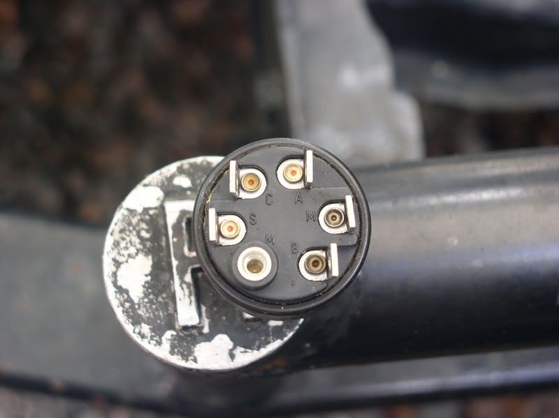
I think the problem is I went from a old withch to a newer switch.
The new switch is like the one in the picture and th old switch has a different configration.

I just woke from my nap, I will be going out in a hour or so, I will let you know how I make out!

Thanks again!!
 
Ok I go back out and the switch I am using is a little different then the one you show, but is a 6 pole switch.

But it doesn't have all the markings on it?? So I go to west marine and they don't carry this switch? so I go to there sister store E& B and they say I can order and have next friday I say no thank you!!

Boaters World was closed as all the mariners cause it is Sunday >:(

So I decide to go ahead and try to get her done. But Mickey has been playing under the dash of this boat!!

as you will see in the pictures, I have all the color wires I am supose to have but they have been rerouted some weird way?

Here you will see the yellow with red is going to black and into the control box coming back out as black??
My guess is this is the Neutral saftey and the black should go to the yellow and red spot on the switch?

Picture_043_Medium.sized.jpg


And here is were it goes and comes, it the wire in the right, the wire on the left is the T&T

Picture_045_Medium.sized.jpg


Then the purple wire comes from the harness and goes to some relay off the switch, but there is a rusted off conection that I can not find any were??

Picture_044_Medium.sized.jpg


I am not sure how it was working in the first place?? But I bet this is why the choke switch doesn't work!!

So do we have a pic any were on how this is supose to really be wired??
 
That would take me some time even with a correct year model diagram. I was expecting a control box situation.
Is it possible the choke switch portion was remote mounted and not in the switch?
Do you have the correct book on the motor to be able to use the wires color codes and routing?
I'll see what mine has. From what I remember there were a couple of different wire routing capabilities and terminations possible.
Skools most likely can pull this off the top of his head  :-/
I can't.
Is anything simple with you? ;D
 
Just to clarify for the possibility of having the wrong harness (usually if they connect, it's correct).
What year and hp was the motor that the wire harness and controls came from?
And the year and hp of this motor is a "86 225hp.
 
Ha Ha nothing is ever simple with me!!!!!!!!

There is no remote switch for the choke, But that doesn't meant there never was??

I just need that color chart skools put up some time back, but I have looked all night and can't seem to find it??

I have a Clymar book, but eletric is not my strong point! The color one was simple to look at for me the simple guy :D

Thanks
 
MJ, I did a yahoo search on evinrude wire color code and Whaler will pop up. Go into it (continouswave.com I think) and click on Johnson/Evinrude color code. I hope this helps.
 
Got a wiring diagram in front of me
What you need??


While I'm waiting, I'll try to take pictures of what I think and post them. ::)
 
Back
Top