Dual Battery Wiring
This article describes several techniques for interconnecting outboard motors and dual batteries. There are two distinct applications: single engine installations and dual engine installations.
Single Engine/Dual Battery
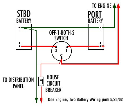
The use of a single engine and dual batteries is one of the most common installations found in outboard powered boats. Interconnection is straightforward. The diagram below shows the typical wiring.
Dual Battery/Single Engine Typical Schematic
NOTE: The battery positive leads are shown in red. The negative leads are shown in green for clarity; code suggests the use of yellow wire. Wiring gauge is determined by current demands and length of the run. Typically 2-AWG is used to connect to the batteries; 10-AWG is used to connect to the distribution panel. The single switch is an OFF-1-BOTH-2 switch.
JWH.
The use of a switch and wiring like this is recommend with dual battery installations. A brief explanation of the operation of the switch in this circuit follows.
In the
OFF position, the two batteries are disconnected from all loads. The OFF position is used when the boat is being stored or otherwise not in use. It prevents any drain from the batteries. This can be useful if a circuit has been accidently left on, say a cabin lighting circuit or similar drain. Such a load can completely discharge a battery in a day or two, leading to an unanticipated dead battery situation when you return to your boat. On some switches a key lock is provided, allowing the switch to locked in the off position. The provides another level of security in preventing the boat from being used when left in storage or unattended.
In the
1 position, all loads and charging currents are connected to the No. 1 battery (the PORT battery in the illustration). Starting current for the engine starter motor is supplied by the PORT battery. When the engine is running, surplus current developed by its charging circuit will flowing into the PORT battery. Current to lighting and other loads will flow from the PORT battery. The STDB battery is completely isolated and has no load current, nor does it receive any charging current.
In the
2 position, all loads and charging currents are connected to the No. 2 battery (the STBD battery in the illustration). Now it supplies current required by starting and running, and it receives all the charging current from the engine. The PORT battery is totally isolated.
In the
BOTH position, the two batteries are connected in parallel. This has a number of implications. Unless the batteries have exactly the same state of charge, the combined voltage to the two batteries in parallel will sag to a voltage somewhat lower than the highest battery's terminal voltage. Current from the higher voltage battery will flow into the lower voltage battery and begin charging it. As long as the state of charge in one battery is higher than the other, the lower battery is more of a load than a source of power. Eventually, the batteries will reach an equilibrium, and they will both have the same terminal voltage. At that point they will both tend to supply current to loads that are attached to them, and they will both receive charging current furnished by the engine.
It would seem like operating in the BOTH position would be beneficial, but that is not always the case. Even thought the batteries will eventually rise or fall to the same terminal voltage when connected together, they will not necessarily become exactly the same. A battery (or any source of electrical engery) can be though of as having an internal resistance. The lower this internal resistance the greater the current it can supply. The internal resistance will also affect how the battery absorbs charging current. Even though they are connected in parallel, it is possible that they will supply unequal currents to the loads, and it is also possible that they will accept unequal currents from an the engine charging source.
If the batteries are significantly different in their age, their type of construction, and their state of charge, this unequal distribution of current can be more significant. To describe the situation in the simplest of terms, when two batteries are connected in parallel, they will probably tend to behave more like the weakest battery of the two than the strongest.
Paralleling the batteries can come in handy in some situations. For example, both batteries may be discharged to a point where neither alone can provide enough current to crank the starter motor, but combined in parallel they can turn the engine over.
If one battery is fully charged and the other is totally discharged, connecting them in parallel (by using the BOTH position) can cause very high currents to flow between the batteries. Extreme heat can be generated by the sudden charging of the discharged battery. Use caution in this situation. It is better to recondition a discharged battery by slowly re-charging it with an AC-operated battery charger.
The arrangement of the contacts of the typical OFF-1-2-BOTH permits the operation of the switch in the range of 1-2-BOTH without ever disconnecting the batteries from the load or the outboard charging circuit. This is important, as it is possible to cause damage to the charging circuit if the battery is disconnected while the engine is running. By choosing the path of rotation of the switch, it is possible to change from
1 to
2 without moving through the
OFF position.


 About the only thing I could add to it would be the recomendation to always use identical batteries in a dual battery situation. That way the drain from them and the recharging of them would be easier to manage. Not always pratical for sure, but better than having two dissimilar units.