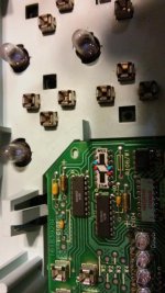
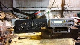
Heres a few pics of what I'm working on. Since my health has deteriated to the point that wrenching is out for me anymore, I have taken up doing some electronics work. I've been wanting to put in a custom gauge cluster into my SUBURBAN for awhile now, so what better excuse to get set up to work with instrumentation. I'm planning on putting in an ESCALADE cluster into my BURB because they have a 120MPH speedo instead of the regular trucks 100MPH, the temp gauge starts off at 100 instead of 160(for some reason GM started teh diesel clusters at 160, I'm guessing so people wouldn't freak out when they seen how long it took for them to warm up, but I have confirmed that the 1st mark should be 100, not 160, just a pet peeve of mine to make everything correct is all), but it has a 6K RPM tach instead of the 5K RPM tach that the DURAMAX needs. Most would say the heck with it, but I'm a stickler for details. I have found a company that will make a custom gauge face overly afor me to correct the tach, work with the 120MPH speedo, and keep the temp gauge starting at 100, but it will either require a signal interface box to correct the tachometer reading, OR to recaibrate the actual tachometer driver circuit. So I'm going to go with the more complex but cheaper solution, and correct the actual tach(I'm also doing this because my ECM outputs a 4 cylinder signal instead of a V8 like the EXCALADE cluster is set up for). And to think what really started me to doing this was my gas gauge needs redampening, so it's bouncing around all over the place while driving.
So I'm getting setup now to go through and redampen the old style air core motors used in older gauge clusters, as well as verify correct gauge movement, check the calibration of the tachometers/speedometers, and correct if neccesary. So far I have a signal generator to simulate the tachometer/speedometer signals, a power supply, syringes, silicone fluid to dampen the gauges, but still need to get a gauge simulator to control the ohms signal to verify correct operation.
This is what makes a mid 90's GM truck cluster tick, and that little white resistor block is what calibrates the tach and speedo. The 2 pins highlighted in blue are for the speedo, and the 2 in red are for the tach. The black sections inside of the white block are a precision resistor that GM used for calibration. They used a laser to cut parts of it until they were calibrated, but over time the cuts break up more so, the resistance goes up, and then the gauge reads higher.
And heres the signal generator in use runnng the tach and speedo in a 98 diesel cluster.
And this is what started me to messing with gauge clusters. My fuel gauge bounces ALL over the place when the fuel in the tank sloshes. GM had a thick silicone oil they put in them when new that slowed the gauge movement, but over time this oil breaks down/dries out, and then you get gauges with torrets. So I'm redampening the air core motors for the gauges, checking there function, and checking the tach/speedo and correcting as neccesary.
http://www.youtube.com/watch?v=XqQrHslLTcM
http://www.youtube.com/watch?v=OIXpyMR9b7Q
So while I'm doing this, I figured I would play with some other gauges as well to try and broaden my horizon.

 Let me look in the shed tomorrow.
